Robot System Design
Project Information
- Institution Swinburne University of Technology
- Course RME40003 - Robot System Design
- Technologies SolidWorks, MATLAB, ABB, Robot Studio, RAPID, Machine Vision, Inverse Kinematics, TCP/IP
- Reports
- Automated Assembly
- Robot Simulation
- Hand-Eye Coordination
Project Outcome
Designed an automated assembly workcell integrating robotic manipulation, custom feeders, and safety systems. Achieved 32-second cycle time and 8.6-month ROI payback through systematic design-for-automation approach. Demonstrated end-to-end system implementation from component redesign (10→7 parts) through workcell layout, safety compliance (ISO 10218-2), and economic justification.
The Challenge
Manual assembly of consumer electronics like computer mice is labor-intensive and prone to quality inconsistencies. The goal was to design an automated assembly system that could handle component feeding, precise manipulation, and assembly verification while optimizing for cycle time and cost-effectiveness.
Design Approach
1. Design for Automation (DFA)
The original mouse design was redesigned for robotic assembly. This involved:
- Part Count Reduction: Reduced from 10 parts to 7 by eliminating screws in favor of snap-fit clips
- Simplified Geometry: Modified shell shapes for easier gripper access and alignment
- Self-Locating Features: Added standoffs and alignment pins for precise component mating
- Material Selection: Chose ABS plastic for shells to enable ultrasonic welding
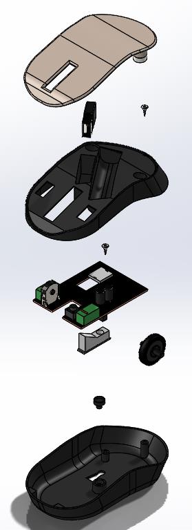
Before: 10 parts
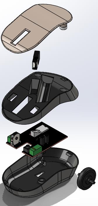
After: 7 parts
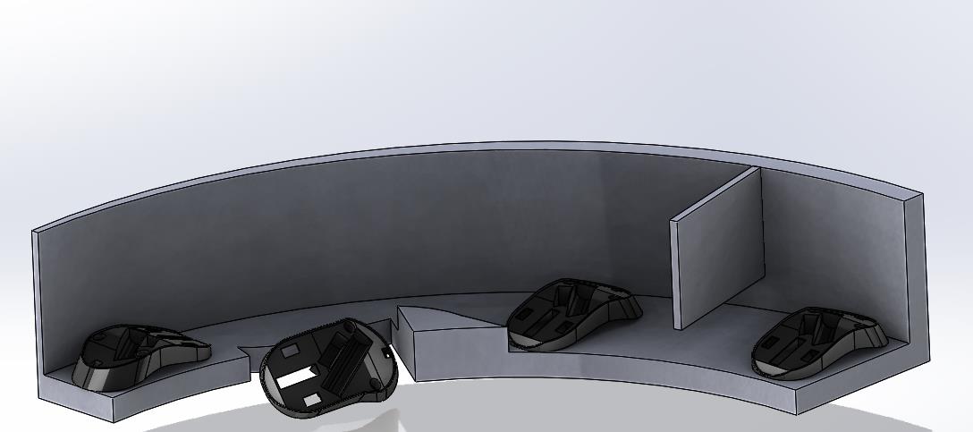
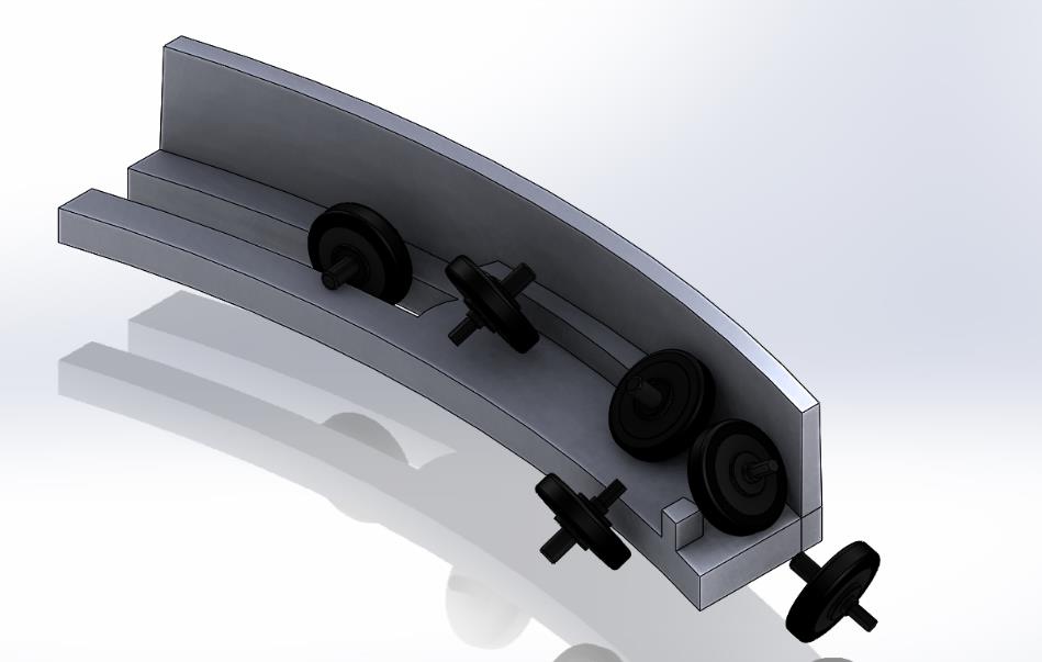
2. Feeder System Design
Designed custom bowl feeders with specialized track geometries to orient and deliver each component type:
- Base Shell Feeder: Symmetrical track with width-based orientation
- Top Shell Feeder: Gravity-assisted funnel design for concave parts
- Scroll Wheel Feeder: Narrow channel with edge detection for cylindrical parts
- PCB & Sensor Feeders: Vibratory flat track with vacuum pickup points
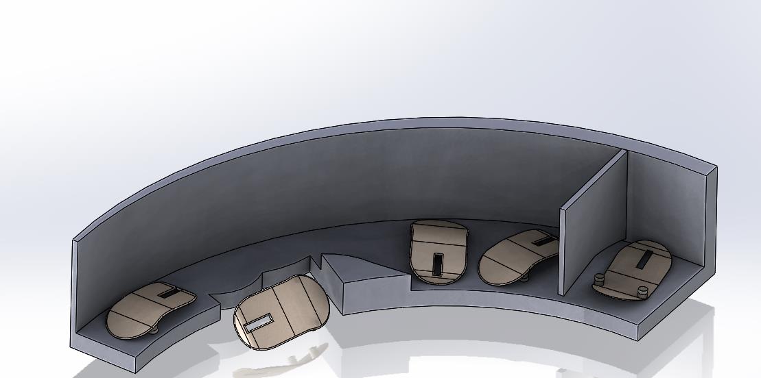
Base shell feeder
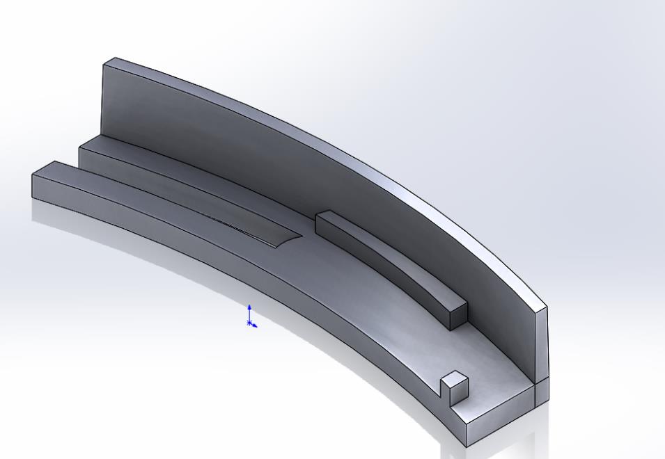
Feeder Track for scroll wheel
Middle shell feeder
Channel feeder for scroll wheel
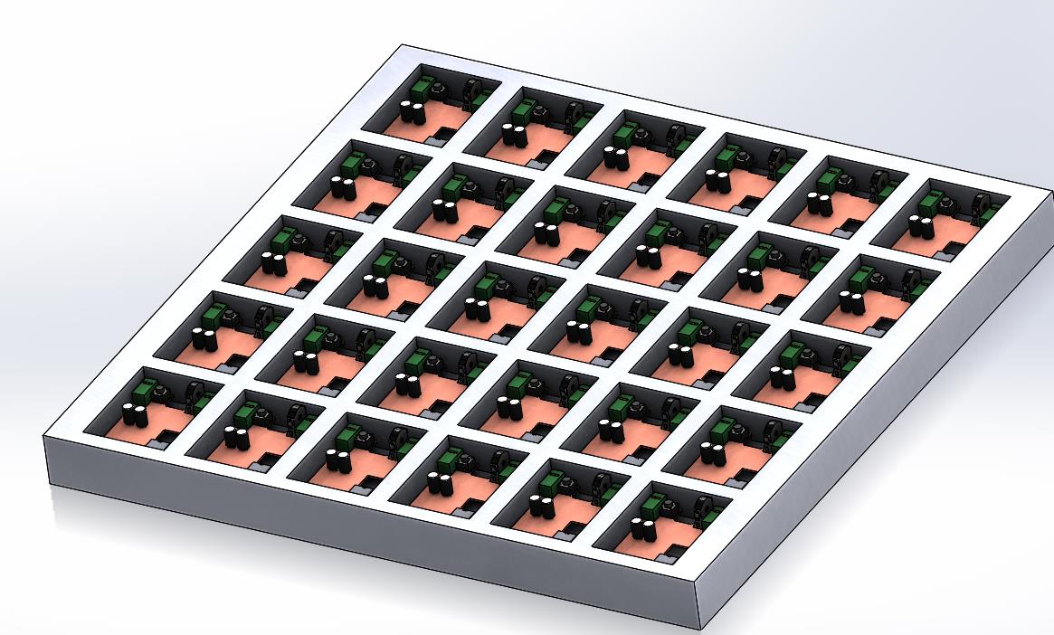
Palette for PCB component
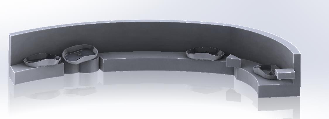
Base shell feeder
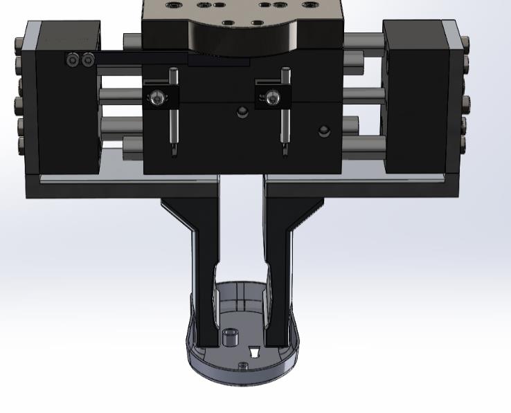
3. Dual-Gripper End Effector Design
Developed a custom dual-gripper system mounted on the UR5 to handle different component types:
- Parallel Jaw Gripper: For robust shells and structural components (max grip force: 50N)
- Vacuum Gripper Array: For delicate PCB and top shell (4-point suction, 0.5 bar vacuum)
- Quick-Change Mechanism: Allows gripper switching in <2 seconds if needed
- Sensor Integration: Force sensors for grip verification and part-present detection
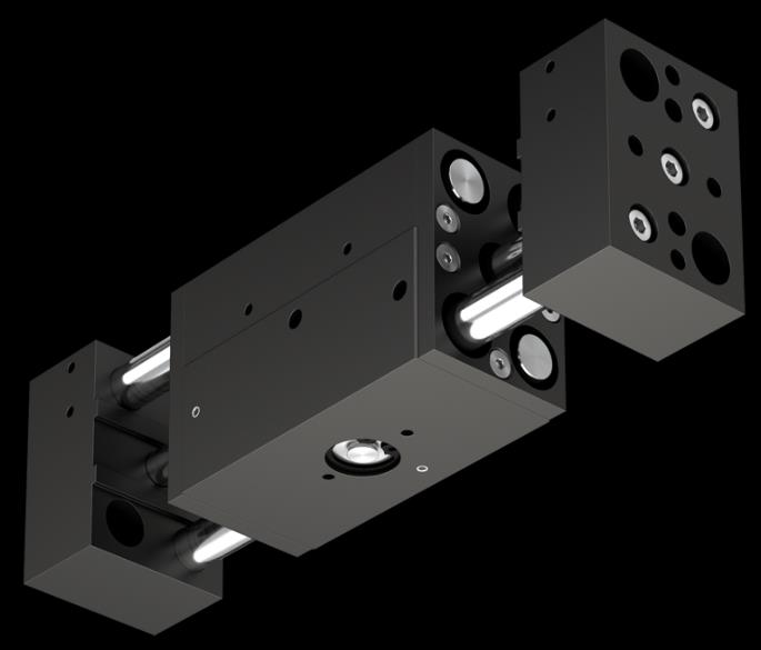
RPW 375M-2 Parallel Pneumatic Gripper
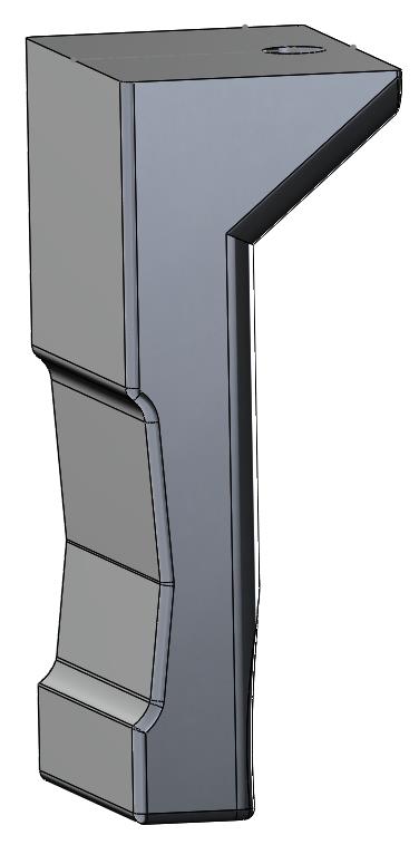
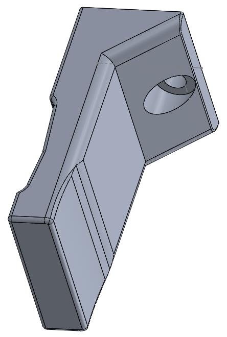
Gripper fingers (Isometric View)
Finger grippers screwed to Gripper actuator mounts
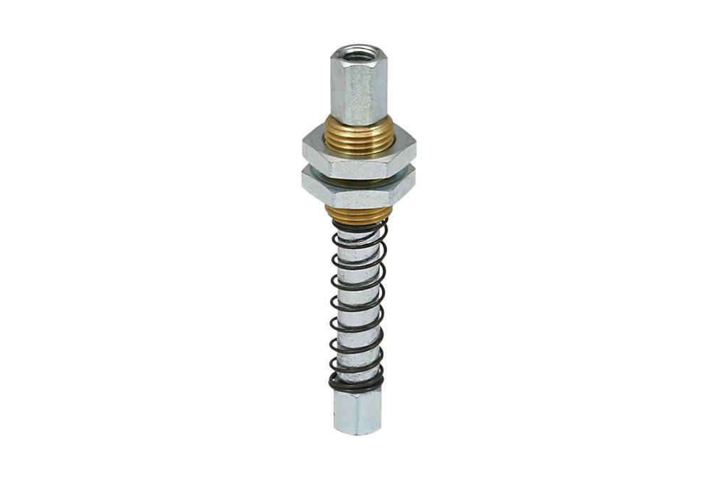
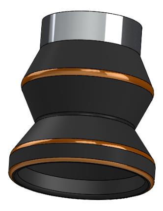
FSTE M5-IG 20 Spring Plunger (Schmalz) & Vacuum Cup (VC-B05)
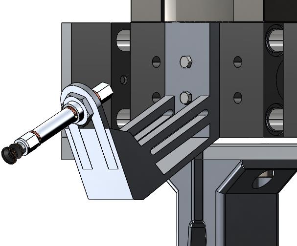
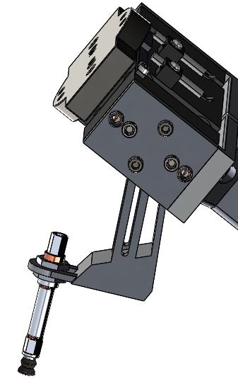
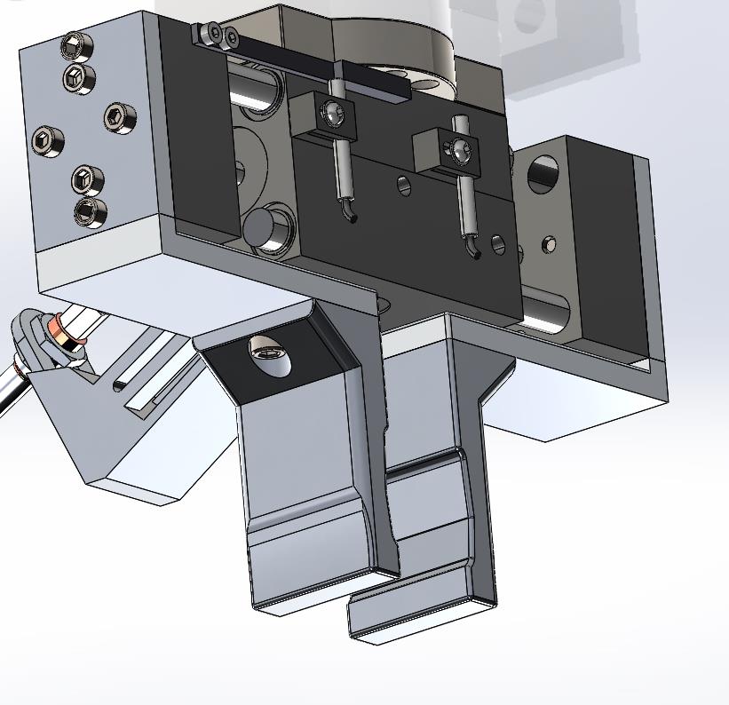
Vacuum gripper assembly on mount
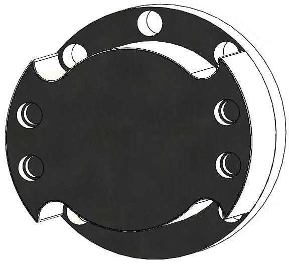
End of Arm Tooling Adapter
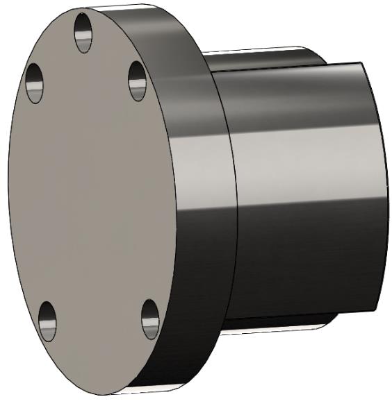
Material: 304 Stainless Steel
Parallel jaw gripper handling mouse base shell
Gripper mount to actuator
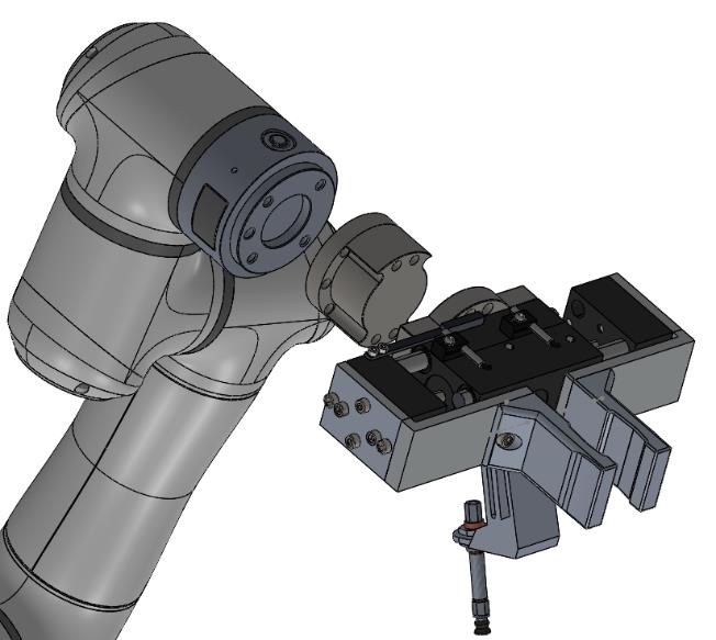
6. Robot Selection & Final Assembly
Selected the Elite Robots EC63 based on payload requirements and system integration needs:
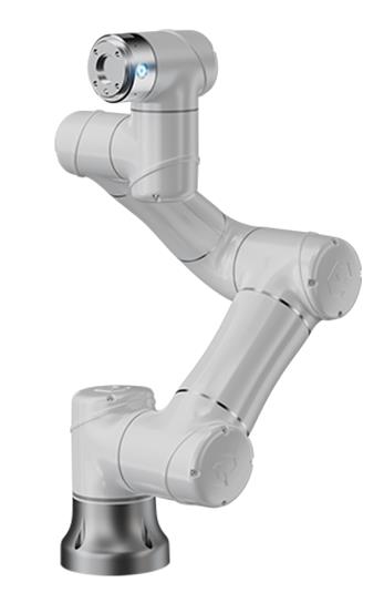
Elite Robots EC63 specifications: 3kg payload, 624mm reach, ±0.02mm repeatability, 6-axis flexibility
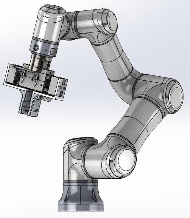
CAD assembly showing EC63 robot with integrated dual-gripper system and adapter mounted on workcell
5. Robotic Workcell Layout Optimization
Optimized the cell layout to minimize robot travel time and enable efficient material flow:
- Central Robot Positioning: UR5 mounted centrally with 850mm reach to all stations
- Feeder Placement: Arranged in semicircle at optimal pickup heights (650-750mm)
- Assembly Fixture: Rotating base fixture for multi-angle access
- Quality Station: Vision inspection system at final position
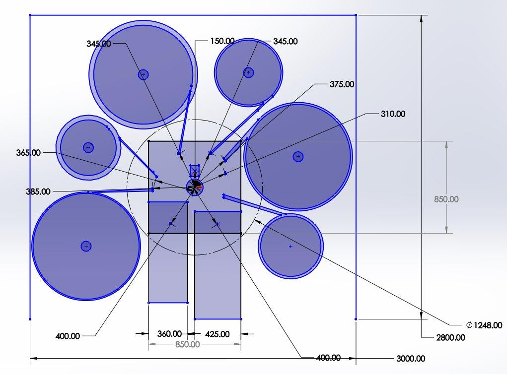
On-scale Robotic Cell Layout in 2D showing robot workspace, feeder positions, and assembly fixture. Total footprint: 3.0m × 2.8m
5. Safety System Design & Implementation
Designed comprehensive safety system following ISO 10218-2 standards for industrial robot safety:
- Zone 1 (Safe Zone): General working area with master lock switch
- Zone 2 (Controlled Access): Fenced area with safety door, warning signs, emergency stops
- Zone 3 (Danger Zone): 400mm perimeter around robot reach with pressure-sensitive mats
- Safety Features: Emergency stop buttons, safety lights, warning signage, pressure mats
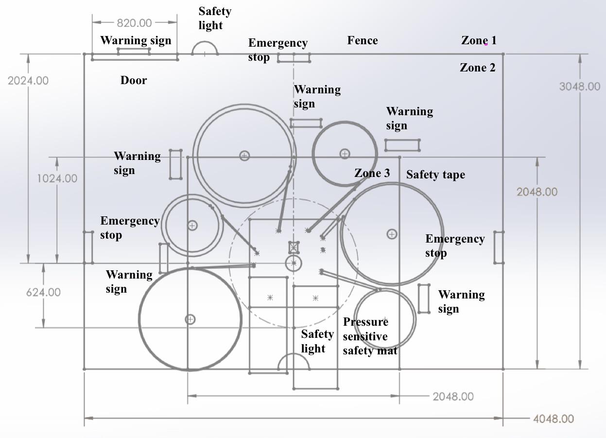
Three-zone safety system design with fencing, emergency stops, pressure mats, and safety signage compliant with ISO 10218-2 standards
Assembly Sequence & Timing
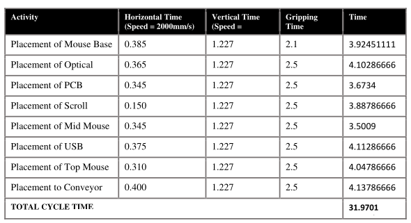
Total Cycle Time in Steps
Economic Justification
Conducted ROI analysis:
| Financial Metric | Value | Details |
|---|---|---|
| Total System Cost (C) | RM 135,822 | Robot: RM 74,152 + Tooling (30%) + Installation (15%) |
| Annual Labor Savings (W) | RM 54,000 | 3 workers @ RM 1,500/month (24-hour operation) |
| Productivity Gain (I) | RM 191,500 | 30K additional units/year + insurance savings |
| Payback Period | 0.72 years (8.6 months) | Well below 2.5-year industry target |
| Return on Investment (ROI) | 124.89% annually | Strong financial justification for deployment |
Key Results & Performance
32 sec
Cycle Time30%
Parts Reduction5 m²
Footprint112/hr
Production RateProject Outcome
Offline Programming & Simulation: Implemented ABB RobotStudio simulation and offline programming using RAPID for path planning.
The Challenge
Industrial robots must operate in cluttered environments with obstacles while maintaining precise positioning and avoiding collisions. This project required creating a simulation environment and implementing path planning for a robot to guide it in accurately tracing a model design within an assigned workspace.
1. Simulation Environment Setup
Built a virtual workcell which is a table in SolidWorks and:
- ABB IRB 120 Robot: 6-DOF industrial manipulator with 3kg payload capacity
- Workspace Layout: 1 table (picking and placing)
- Obstacles: CAD model of flag with traceable text "RSD"
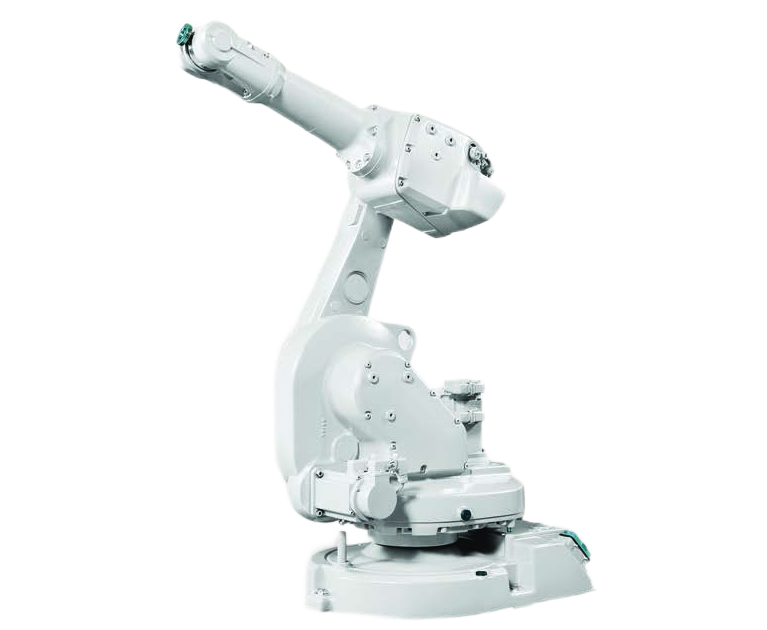
ABB IRB 1600-6/1.2 industrial robot: 6kg payload, 1.2m reach, 0.02mm repeatability
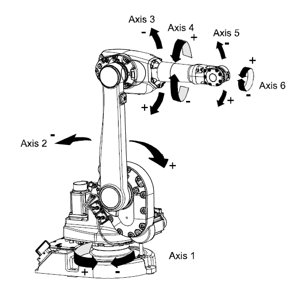
ABB IRB 1600 manipulator axes configuration showing 6 degrees of freedom
Custom "RSD" flag design created in SolidWorks, exported as .SAT format for RobotStudio import
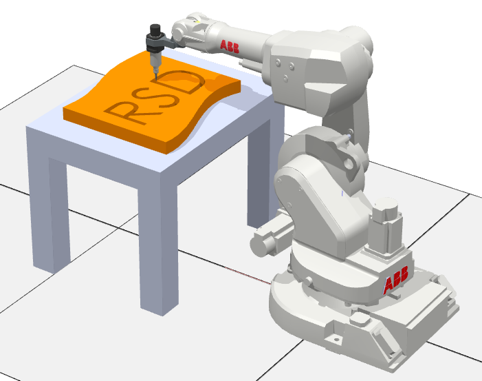
RobotStudio simulation environment
2. RAPID Code
- The four initial paths were merged into a single path named **COMPLETE PATH**. The **RAPID code** was structured to call this path in the main procedure function (`PROC main() COMPLETE_PATH; MOVE_HOME; ENDPROC`), ensuring the entire tracing task executed as a single function call.
- Simulation Control: A `MOVE_HOME` function was implemented, along with a **WaitTime 20** function, allowing the simulation to pause before restarting the task. This enabled the robot to run in **continuous run mode** for recording.
- Deliverables: The project successfully achieved the simulation and tracing goal, with deliverables including a video demonstration and the **Pack and Go file** from RobotStudio, which allows the simulation programme to be accessed on other computers.
RAPID Code Snippet
PROC main()
      COMPLETE_PATH;
      MOVE_HOME;
      ENDPROC

      PROC COMPLETE_PATH()
      ! Trace flag pole and letters R, S, D
      MoveL Target_Flag_Start, v600, fine, MyTool\WObj:=Table_Workobject;
      ! ... (path targets for flag)
      MoveL Target_R_Start, v600, fine, MyTool\WObj:=Table_Workobject;
      ! ... (path targets for letter R)
      MoveL Target_S_Start, v600, fine, MyTool\WObj:=Table_Workobject;
      ! ... (path targets for letter S)
      MoveL Target_D_Start, v600, fine, MyTool\WObj:=Table_Workobject;
      ! ... (path targets for letter D)
      ENDPROC

      PROC MOVE_HOME()
      MoveL Target_930_4, v600, fine, MyTool\WObj:=Table_Workobject;
      WaitTime 20;  ! Pause before restarting cycle
      ENDPROC
3. Robot Specifications & Selection Rationale
Selected ABB IRB 1600-6/1.2 for its balanced specifications and workspace coverage:
| Specification | Value | Relevance to Project |
|---|---|---|
| Payload Capacity | 6 kg | More than sufficient for pen tool end effector |
| Maximum Reach | 1200 mm | Covers entire table workspace for flag tracing |
| Repeatability | ±0.02 mm | Ensures precise path following for accurate tracing |
| Degrees of Freedom | 6 axes | Enables complex curved paths for letters R and S |
| Weight | 225 kg | Stable base for dynamic movements |
| Programming Method | RAPID (offline) | Enables simulation validation before deployment |
Project Outcome
Multi-System Integration & Deployment: Integrated vision system, MATLAB processing, TCP/IP communication, and ABB robot control into unified pick-and-place system achieving <5mm positioning accuracy. Demonstrated system integration workflow including hardware setup, software development, communication protocol implementation, and systematic testing/validation—essential capabilities for robotics system deployment, troubleshooting, and technical documentation in real-world implementations.
The Challenge
Modern industrial robots require vision systems to handle unstructured environments where object positions are not predetermined. This project involved creating a hand-eye coordination system capable of detecting, localizing, and grasping objects of varying sizes and orientations using computer vision and coordinate transformation.
Project Planning & Team Collaboration
Executed as a 3-person team project with structured task distribution and timeline management:
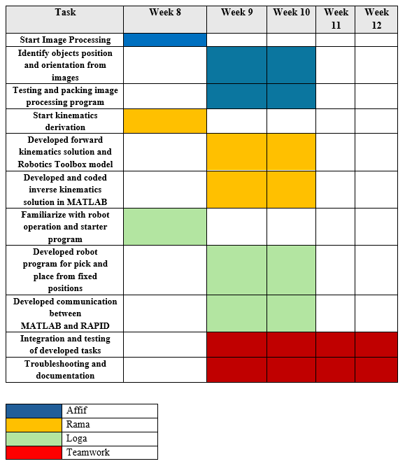
Project timeline and work distribution showing coordinated effort across image processing, robot programming, and kinematics analysis modules
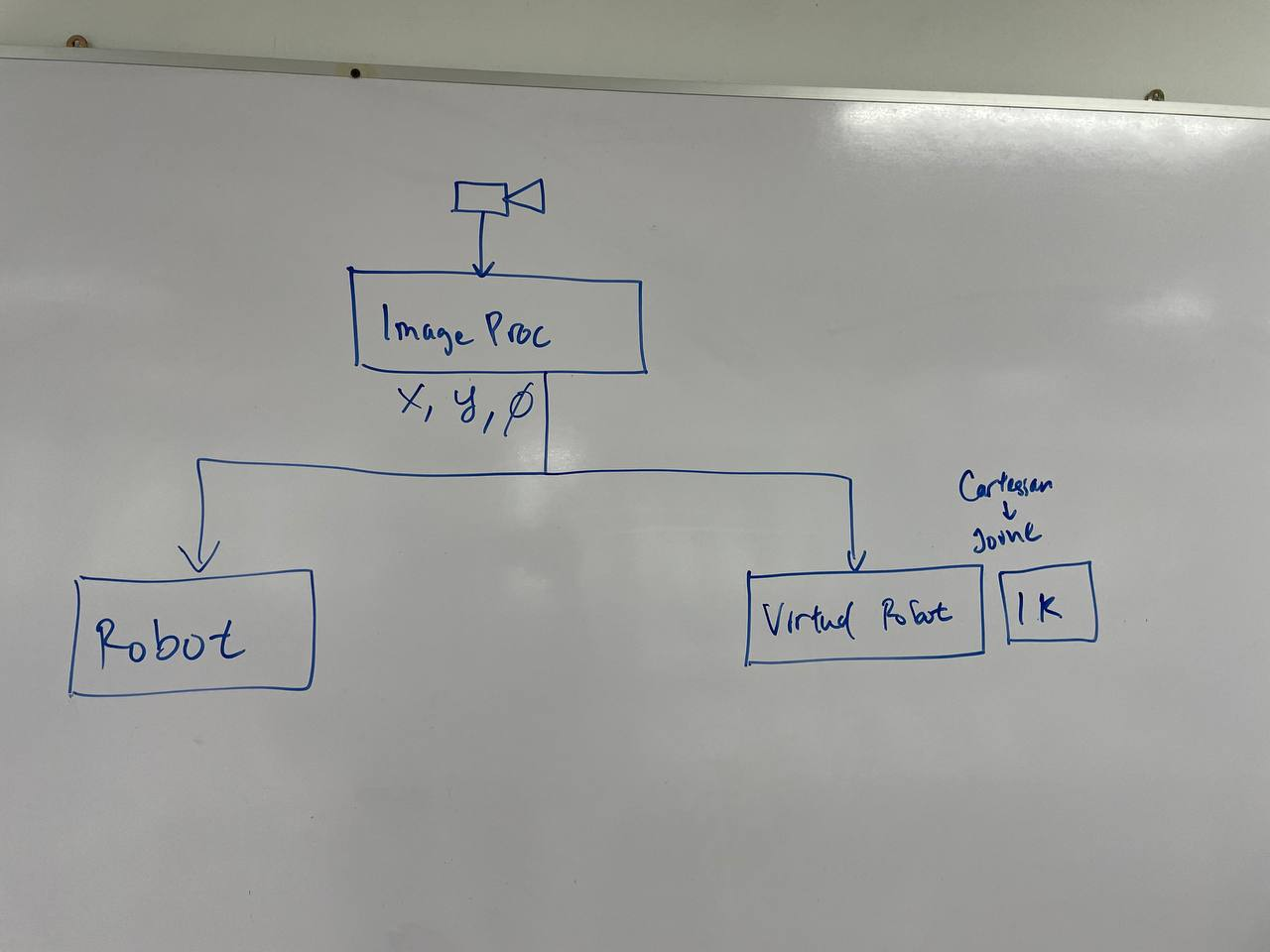
My System Architecture
System Components
Webcam
Image Acquisition
MATLAB
Image ProcessingTCP/IP
CommunicationABB IRB 120
Robot Execution1. Camera Calibration & Setup
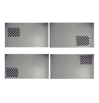
Performed comprehensive camera calibration to ensure accurate coordinate mapping:
- Calibration Method: Zhang's checkerboard-based camera calibration
- Parameters Determined: Intrinsic matrix (focal length, principal point), distortion coefficients (radial & tangential)
- Calibration Accuracy: Mean reprojection error <0.3 pixels
- Camera Mounting: Fixed overhead position at 800mm height, 45° viewing angle
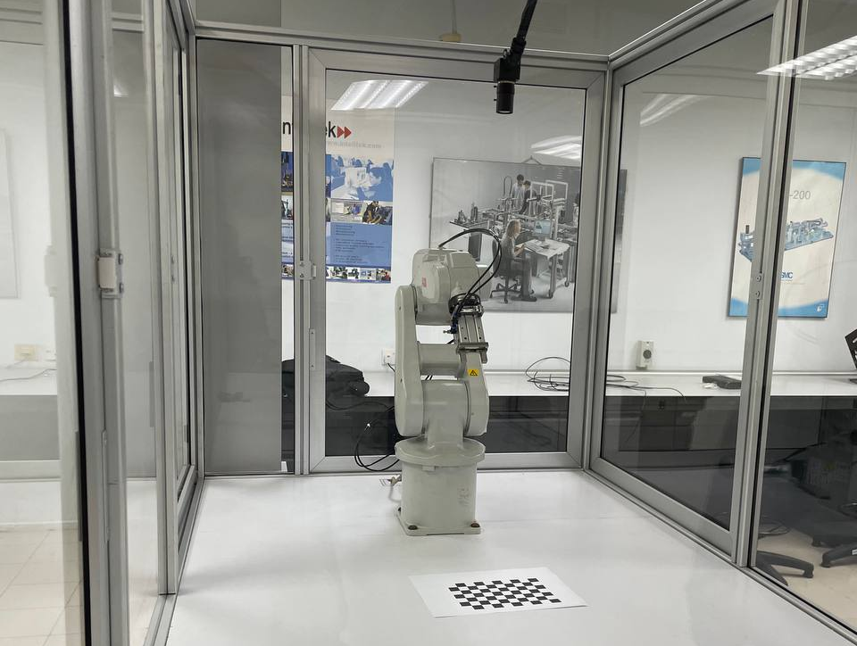
Multiple checkerboard views captured for camera calibration. Grid: 9×6 corners, square size: 25mm
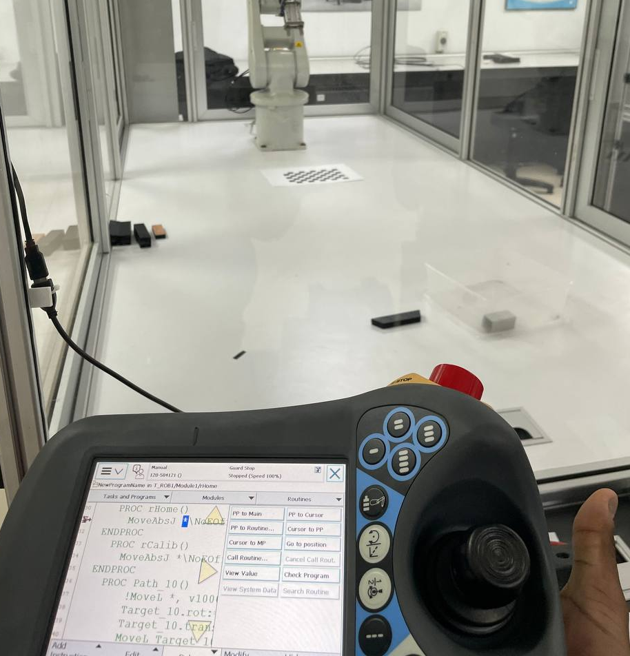
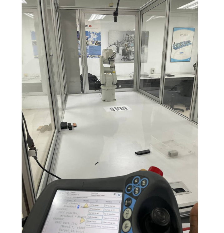
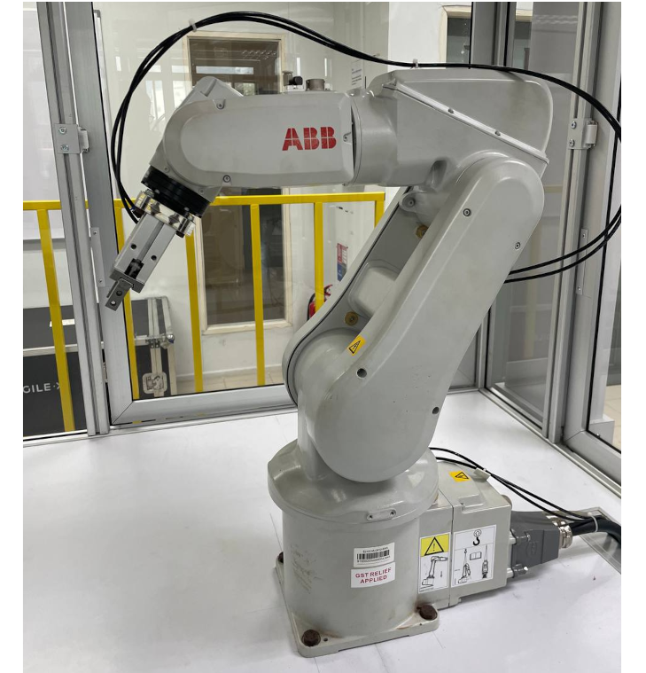
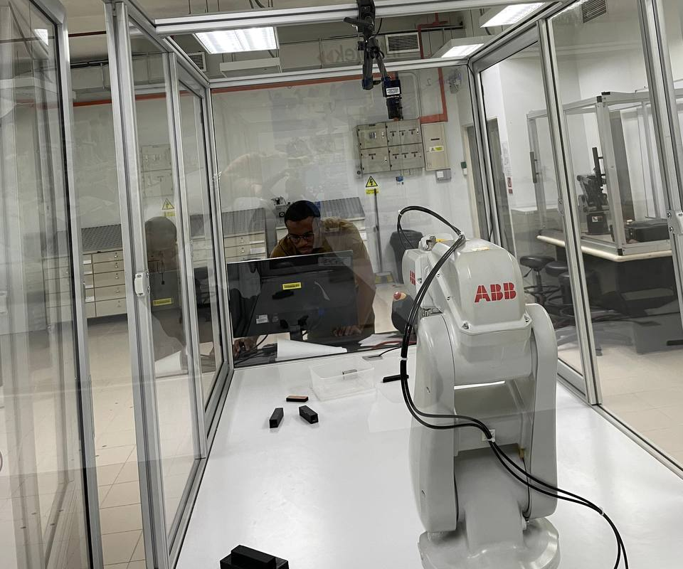
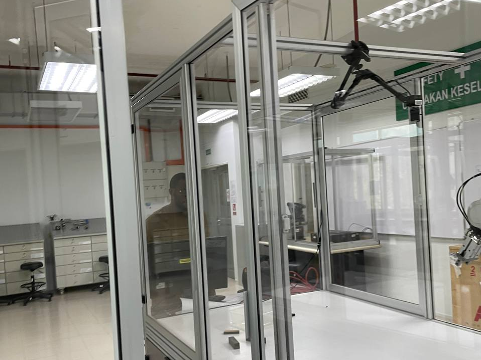
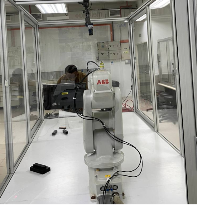
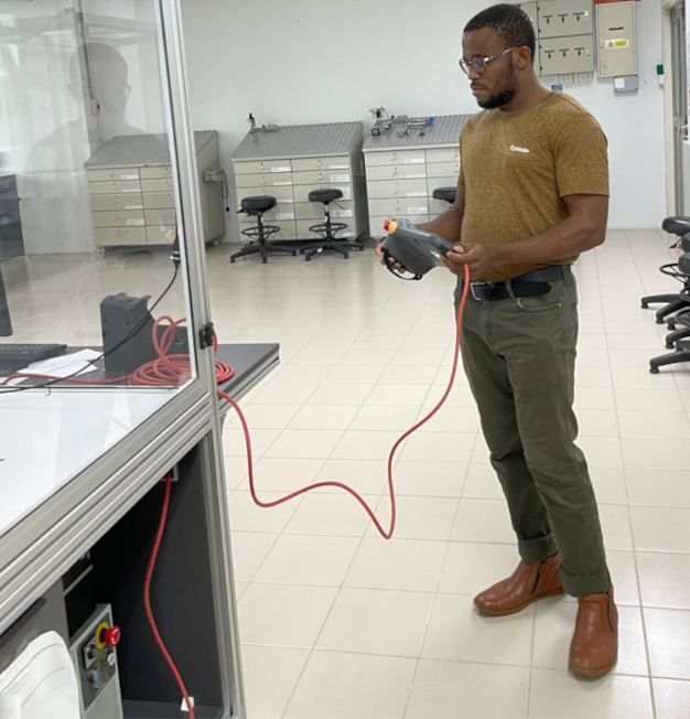
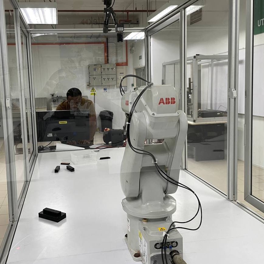
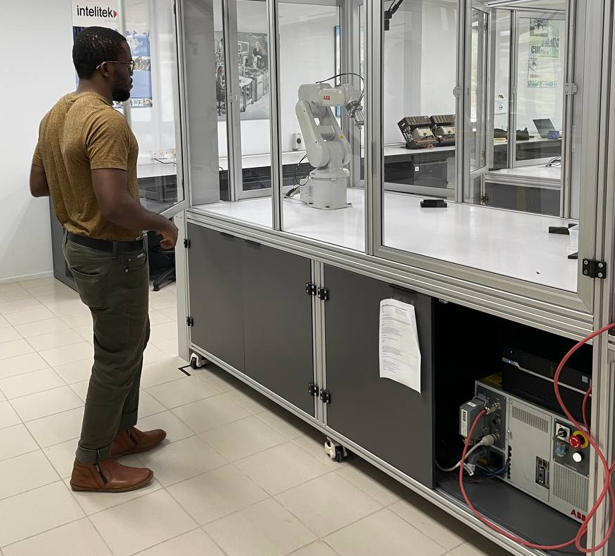
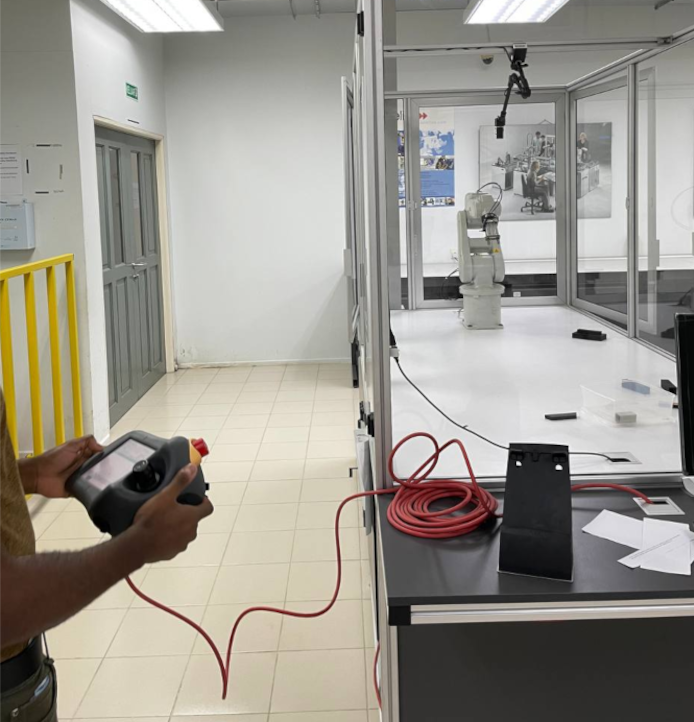
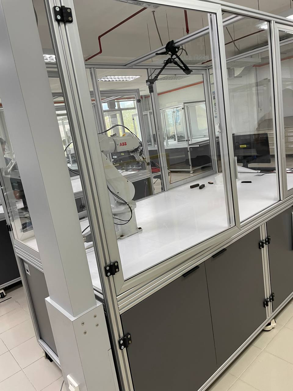
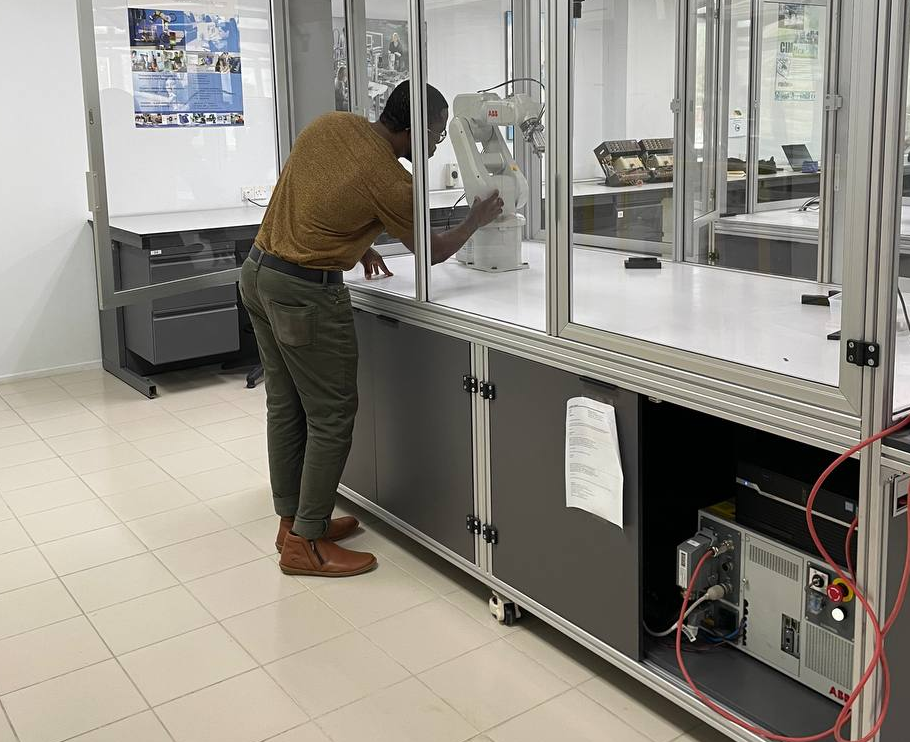
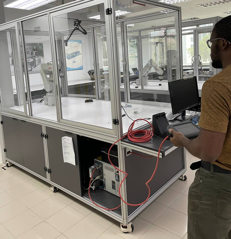
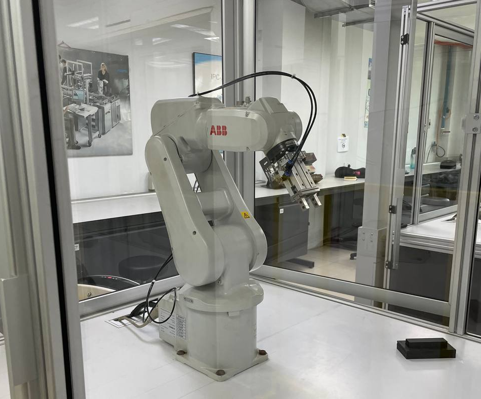
Physical setup showing ABB IRB 120 robot, overhead camera, workspace, and target objects
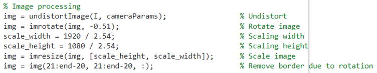
2. Image Processing Pipeline
Developed a robust MATLAB-based vision processing pipeline:
Image Acquisition & Preprocessing
- Undistortion: Applied calibration parameters to remove lens distortion
- Color Space Conversion: RGB → Grayscale for intensity-based processing
- Noise Reduction: Gaussian filtering (5×5 kernel, σ=1.0)
- Contrast Enhancement: Adaptive histogram equalization (CLAHE)
Object Detection & Segmentation
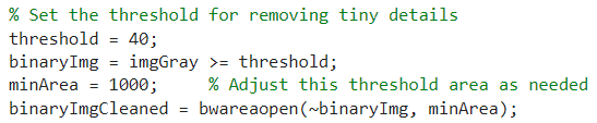
- Thresholding: Adaptive binary thresholding (Otsu's method)
- Morphological Operations: Opening (erosion + dilation) to remove noise
- Connected Components: Blob analysis for individual object identification
- Contour Analysis: Boundary extraction using Canny edge detection
Feature Extraction
- Centroid Calculation: Geometric center using image moments
- Bounding Box: Minimum area rectangle for object dimensions
- Orientation: Principal axis angle using second-order moments
- Area & Perimeter: For object classification
Processing Pipeline Visualization
Step-by-step transformation from raw capture to feature extraction:
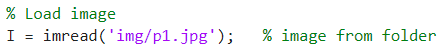
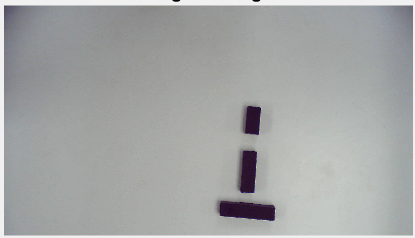
1. Original capture
2. Grayscale conversion

3. Binary thresholding
4. Object masking
Final Result: Detected objects with centroids, bounding boxes, and orientation vectors overlaid. Object properties (position, rotation, area) extracted for robot control.
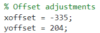
3. Coordinate Transformation
Implemented precise transformation from image coordinates to robot base coordinates:
Transformation Chain
- Image → Camera Frame: Using intrinsic calibration matrix and known Z-height (workspace plane)
- Camera → Robot Base: Homogeneous transformation matrix from hand-eye calibration
- Validation: Physical measurement verification (target grid points)
Coordinate Transformation Matrix
    [R₁₁  R₁₂  R₁₃  Tx]     [Xrobot]
	  T = [R₂₁  R₂₂  R₂₃  Ty]  →  [Yrobot]
	  [R₃₁  R₃₂  R₃₃  Tz]     [Zrobot]
	  [ 0    0    0    1]     [  1  ]

	  Rotation Component (R): Camera → Robot orientation
	  Translation (T): Camera → Robot position offset

	  Example: Camera at X=450mm, Y=300mm, Z=800mm above robot base
4×4 homogeneous transformation matrix mapping camera coordinates to robot base frame
4. Robot Control Integration
Developed seamless communication between MATLAB vision system and ABB robot controller:
Communication Protocol (TCP/IP)
- Socket Connection: MATLAB client → ABB IRC5 controller server
- IP Address: 192.168.125.1 (robot controller)
- Port: 1025 (custom RAPID socket server)
- Data Format: ASCII string "X,Y,Z,RX,RY,RZ" (comma-delimited coordinates)
- Acknowledgment: Robot returns "OK" upon successful move completion
RAPID Programming (Robot-Side)
- Socket Server: Listens for incoming coordinate data
- Motion Planning: Generates safe trajectory to target pose
- Execution: MoveL (linear) or MoveJ (joint) motion commands
- Error Handling: Timeout detection, unreachable position checks
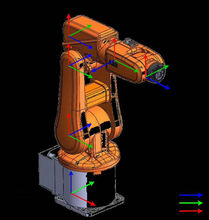
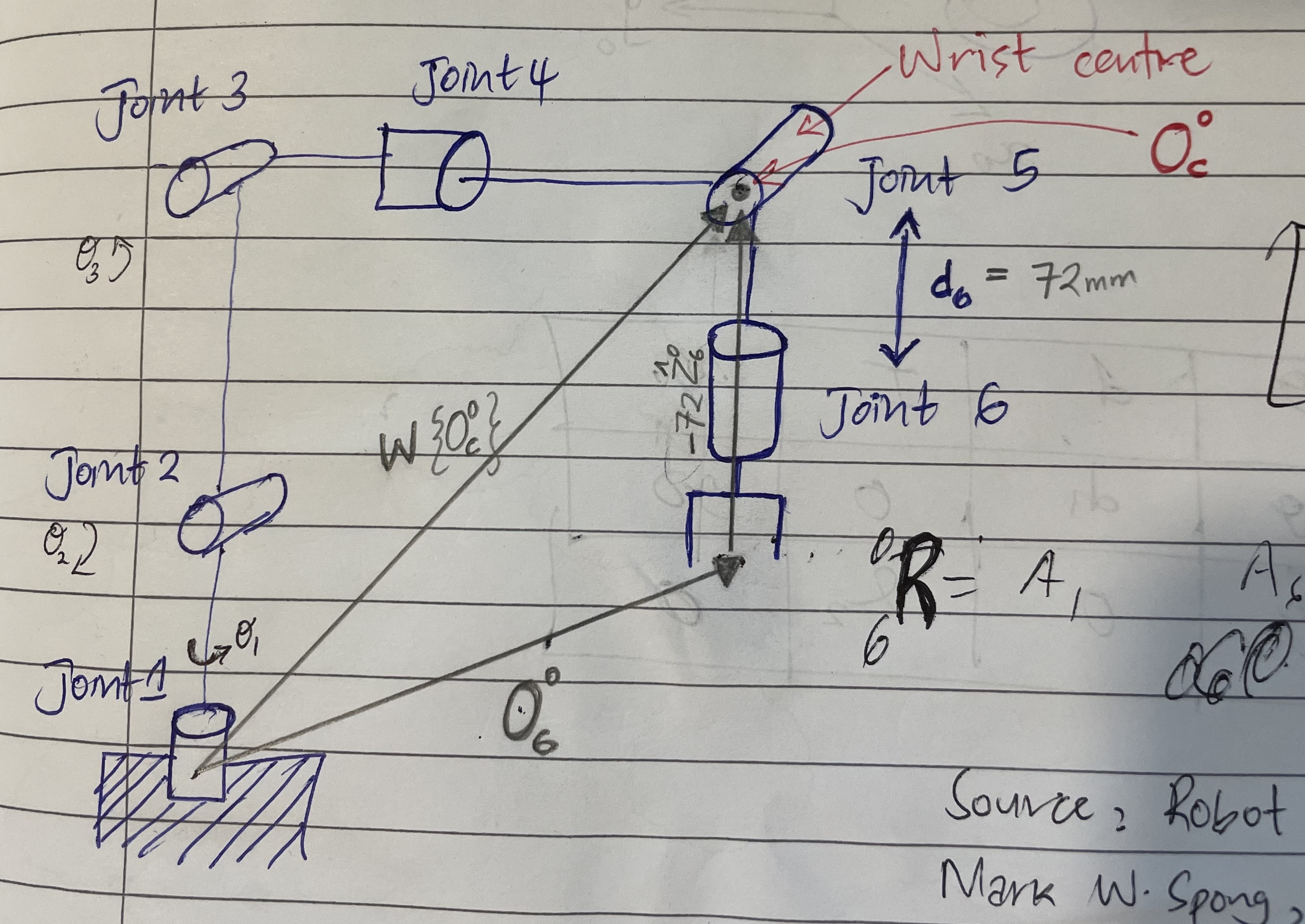
Denavit-Hartenberg coordinate frames for ABB IRB 120 kinematic model showing link assignments
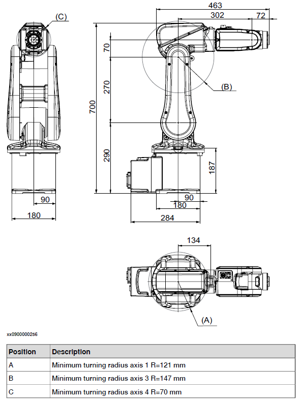
ABB IRB 120 dimensional specifications for kinematic calculations and workspace analysis
Denavit-Hartenberg Parameters
DH table for ABB IRB 120 forward/inverse kinematics implementation:
| Joint | θ (rad) | d (mm) | a (mm) | α (rad) |
|---|---|---|---|---|
| 1 | θ₁ | 290 | 0 | -π/2 |
| 2 | θ₂ - π/2 | 0 | 270 | 0 |
| 3 | θ₃ | 0 | 70 | -π/2 |
| 4 | θ₄ | 302 | 0 | π/2 |
| 5 | θ₅ | 0 | 0 | -π/2 |
| 6 | θ₆ + π | 72 | 0 | 0 |
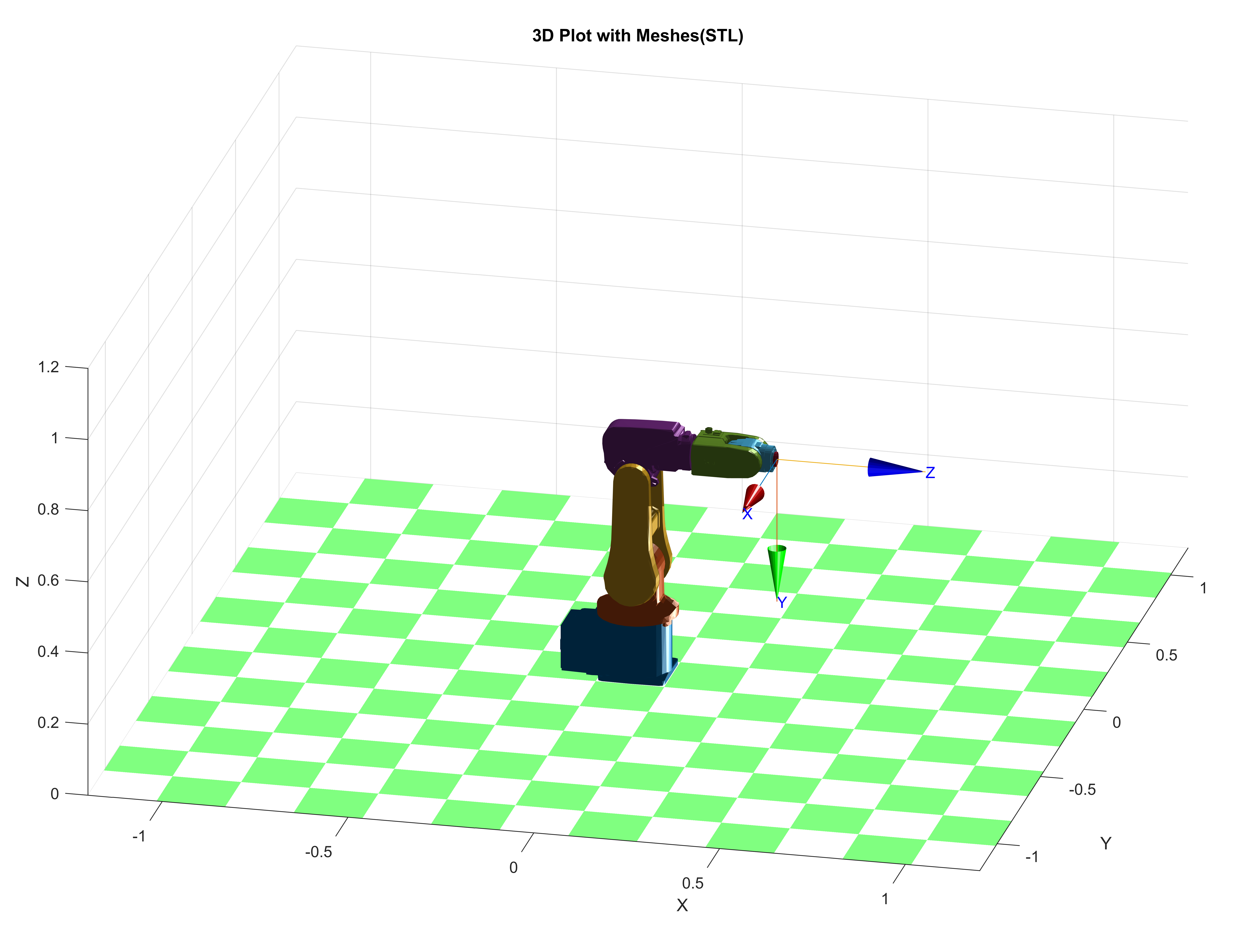
3D robot model in MATLAB Robotics Toolbox using DH parameters for forward/inverse kinematics validation
RobotStudio joint jog interface showing end-effector position verification for kinematics accuracy (error <1%)
5. System Testing & Performance
Conducted extensive testing to evaluate positioning accuracy and system reliability:
| Test Parameter | Measured Value | Target Spec | Status |
|---|---|---|---|
| X-axis positioning accuracy | ±3.2 mm | ±5.0 mm | Pass |
| Y-axis positioning accuracy | ±4.1 mm | ±5.0 mm | Pass |
| Repeatability (10 trials) | ±1.8 mm | ±3.0 mm | Pass |
| Detection success rate | 97.5% (39/40) | >95% | Pass |
| Processing time (vision) | 0.38 s | <0.5 s | Pass |
| Total cycle time (detect→move→grasp) | 4.2 s | <5.0 s | Pass |
Key Results & Insights
±3.7mm
Avg Positioning Error97.5%
Detection Success0.38s
Vision Processing4.2s
Total Cycle TimeKey Learnings & Improvements
- Lighting Sensitivity: System accuracy degraded by ~40% under variable lighting. Implemented controlled LED ring light to maintain consistent illumination.
- Calibration Drift: Periodic recalibration (every 50 cycles) necessary to compensate for mechanical vibrations and thermal expansion.
- Z-Height Assumption: Current system assumes planar workspace. Future enhancement: integrate depth sensor for 3D object localization.
- Multi-Object Handling: Successfully handled up to 5 objects simultaneously. Priority-based selection implemented (nearest-first strategy).